
Les échangeurs de chaleur sur cuves de traitement sont utilisés dans divers procédés technologiques, notamment pour le traitement thermique de produits stockés ou mélangés. Ces types de cuves sont utilisés dans les industries agroalimentaire, chimique, pétrochimique et pharmaceutique.
Ces échangeurs de chaleur à cuve sont utilisés pour le chauffage, le refroidissement et la régulation de la température dans des procédés technologiques tels que la pasteurisation, la fermentation, la liquéfaction du moût, la cuisson, la synthèse chimique et le tempérage. FME Food Machinery Europe Sp. z oo est implantée en Pologne depuis 2007 et conçoit et fabrique des machines, des équipements et des lignes de production pour l'industrie agroalimentaire, notamment pour la transformation des fruits et légumes.
Automatisation de la production d'échangeurs de chaleur à serpentin sur les cuves de traitement
1. Application des échangeurs de chaleur dans les réservoirs
Les échangeurs de chaleur sur cuves de process sont utilisés dans divers procédés technologiques, notamment le traitement thermique de produits stockés ou mélangés. Ces cuves sont employées dans les industries agroalimentaire, chimique, pétrochimique et pharmaceutique. Leurs échangeurs de chaleur servent au chauffage, au refroidissement et à la régulation de la température dans des procédés tels que la pasteurisation, la fermentation, la liquéfaction du moût, la cuisson, la synthèse chimique et le tempérage. La société FME Food Machinery Europe Sp. z oo, implantée en Pologne depuis 2007, est spécialisée dans la fabrication de machines, d'équipements et de lignes de process destinés à l'industrie agroalimentaire, notamment pour la transformation des fruits et légumes.
L'amélioration continue de la qualité de nos produits et services exige des investissements dans de nouvelles solutions technologiques afin de répondre aux attentes de nos clients, de conquérir de nouveaux marchés et d'acquérir un avantage concurrentiel. C'est pourquoi notre entreprise a décidé d'optimiser la production de cuves de process utilisées dans l'industrie agroalimentaire, notamment pour la fabrication de boissons, jus, ketchup, purées de fruits, confitures, fourrages, mousses de fruits, chocolats et sirops. Les cuves de process figurent parmi les équipements les plus utilisés dans la production alimentaire, et ce secteur manifeste une demande constante de produits et de solutions technologiques innovants. De par leur fonction, les cuves peuvent servir au stockage, à la régulation thermique ou encore être utilisées pour des procédés thermiques. Le besoin d'utiliser une cuve pour le mélange, le chauffage, le refroidissement, le maintien en température ou le stockage d'un produit se fait sentir à différentes étapes du processus technologique. Les cuves de process sont donc un élément essentiel de la plupart des lignes de production de l'industrie agroalimentaire.
2. Simulation informatique des composants de serpentin sur une cuve de traitement
Grâce à l'utilisation du logiciel de CAO SolidWorks au sein du bureau d'études, une série de simulations informatiques ont été réalisées afin de raccourcir le temps nécessaire au développement de la section transversale optimale de la bobine profilée et de réduire ses coûts de fabrication.
Les hypothèses utilisées pour réaliser les simulations informatiques permettant d'obtenir le profil de serpentin optimal étaient les suivantes : résistance à une pression d'au moins 6 bars, aptitude au formage plastique (roulage et enroulement sur la paroi du réservoir), faible sensibilité aux variations de pression et de température, forte résistance à l'entartrage, faible résistance à l'écoulement du fluide caloporteur, haute résistance à la corrosion et faible masse. Ces simulations informatiques ont permis d'obtenir la section transversale optimale du serpentin.
3. Recherche et développement, recherche interne
Cette section transversale a été réalisée par pliage sur presse plieuse, puis soudée manuellement au TIG sur une tôle plane. L'élément ainsi préparé a été soumis à un essai hydrostatique afin d'évaluer sa déformation et sa résistance à la pression. Nos recherches ont démontré que la forme de la bobine conçue résistait à une pression de service de 140 bar à température ambiante sans défaillance. La pression d'essai était limitée par les capacités du dispositif d'essai hydrostatique utilisé pour réaliser des tests dans des conditions de résistance à la pression réelles. Une bobine de 1200 mm de long a été fabriquée pour ces essais.
À l'issue du projet de recherche, les solutions de conception et technologiques développées lors des travaux de R&D ont été testées en conditions réelles. Une station technologique automatisée a ainsi été conçue et développée pour la production d'une série de cuves de traitement.
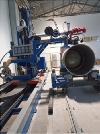
4. Conception d'une station automatisée pour la production d'échangeurs de chaleur sous forme de serpentin sur les parois des cuves de traitement.
L'hypothèse principale de ce projet était que, dans un seul cycle technologique, la bobine était formée, enroulée et simultanément soudée à l'enveloppe extérieure.
Les principaux composants de cette station sont : une colonne-flèche, sur le bras de laquelle est montée une unité de soudage comprenant deux torches de soudage TIG avec alimentation en fil dans le bain de fusion ; une machine à profiler les canaux, fixée à la colonne-flèche ; et un actionneur à force de pression réglable. Cet actionneur est doté d'un galet de pression fixé à l'extrémité de la tige de piston, qui assure le profilage du canal de la bobine jusqu'à la surface extérieure de la paroi du réservoir, pour un diamètre donné. Ceci permet une adaptation automatique du profil du canal au diamètre extérieur du réservoir. Le profil de la bobine est formé par laminage. La machine à profiler de la station de soudage comprend cinq paires de cylindres, chacune entraînée par un motoréducteur. La forme souhaitée du profil de la bobine est obtenue par le passage successif du laminoir à travers différentes paires de cylindres, ce qui accroît la déformation plastique et permet d'obtenir la géométrie de canal adéquate. Le bras de la colonne-flèche de la station de soudage est monté pivotant sur un chariot lui-même fixé sur le premier rail par l'intermédiaire d'une couronne de rotation. La rotation de la colonne et du bras est assurée par une transmission par engrenages et un servomoteur. Le second rail supporte un support à rouleaux actif et un support à rouleaux passif, supportant une cuve de 1200 à 3200 mm de diamètre. Le support à rouleaux actif impose la rotation de la cuve en fonction de la vitesse de soudage. Le poste de soudage est équipé d'un positionneur inclinable et rotatif permettant la réalisation de bobines sur des cuves de 780 à 1200 mm de diamètre. Un distributeur de gaz est monté côté laminoir pour protéger la racine du profil de la bobine et intègre également un élément de mise à la terre permettant la fermeture du circuit de soudage. La barre plate de la bobine est montée devant le laminoir. Le soudage est réalisé par procédé GTAW sous protection gazeuse inerte, avec de l'azote comme gaz formateur pour protéger la racine de la soudure à l'intérieur du profil de la bobine, au point de soudage. La cuve est mise en rotation et les positions de la torche sont modifiées simultanément avec le chariot de la colonne et du bras et le laminoir, qui se déplacent en ligne droite de manière synchronisée avec la rotation de la cuve. Deux appareils de soudage d'une intensité maximale de 500 A, fabriqués par Closs Polska, sont utilisés comme sources d'alimentation pour le procédé GTAW. Ces appareils maintiennent une longueur d'arc constante entre le bain de fusion et la torche, quelle que soit la précision de la paroi du réservoir. Cette distance dépend de la tension d'amorçage : plus l'arc est long, plus la tension est élevée. Ce signal est transmis à l'automate programmable (PLC), qui, grâce à un algorithme approprié, envoie un signal de commande au servomoteur. Ce dernier actionne le déplacement de la torche et maintient ainsi la longueur d'arc souhaitée. Lors de la fabrication du spiral sur la surface extérieure de la paroi du réservoir, l'automate programmable synchronise la vitesse de rotation du réservoir avec la vitesse linéaire du chariot colonne-flèche, l'angle de la colonne-flèche, la vitesse de formation du canal, la vitesse d'alimentation du canal sur la paroi du réservoir et la puissance du brûleur.
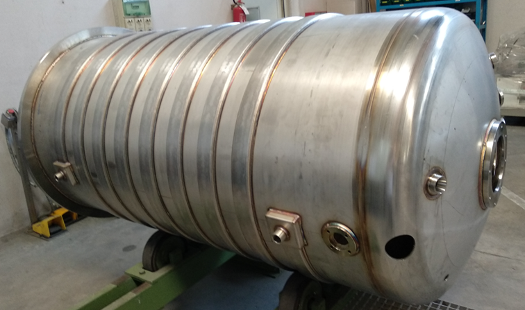
5. Réservoirs équipés d'échangeurs de chaleur sur la surface extérieure de la coque, fabriqués sur une station robotisée.
Les échangeurs de chaleur fabriqués sur cette station garantissent une grande répétabilité et une qualité optimale des unités de traitement complètes, tout en éliminant ou en minimisant les défauts liés au soudage manuel. Les dimensions géométriques optimales du serpentin soudé permettent une alimentation en haute ou basse pression. Ce procédé de fabrication de l'échangeur de chaleur sur la paroi de la cuve de traitement permet de maintenir une surface interne intacte de cette dernière, avec une rugosité inférieure à Ra 0,8 µm. Cette solution permet l'utilisation d'un produit semi-fini (barre plate) pour la fabrication d'un serpentin uniforme jusqu'à 300 mètres de long. L'utilisation de paramètres de soudage optimaux, en fonction de l'épaisseur de la paroi de la cuve, de l'épaisseur du profil du serpentin et de la vitesse de soudage, permet la production de joints soudés répétables à partir d'aciers AISI 316L et AISI 304, offrant une haute résistance à la corrosion, une zone affectée thermiquement réduite, une résistance aux chocs élevée et la possibilité d'utiliser des pressions plus élevées pour les fluides caloporteurs ou réfrigérants. De plus, le serpentin soudé sur la surface extérieure de la paroi du réservoir renforce la structure car il est constitué d'une seule pièce de matériau qui ne surchauffe pas et présente une faible déformation due à la soudure. Par conséquent, des tôles plus fines peuvent être utilisées pour la paroi, ce qui augmente la conductivité thermique entre le fluide caloporteur et le fluide contenu dans le réservoir.
La station technologique ainsi construite a été soumise à une demande de protection par brevet sous le numéro P433821 le 8 mai 2020.
Une série de types de réservoirs avec une enveloppe en spirale soudée des deux côtés à l'enveloppe latérale du réservoir dans une station automatisée
|
Typ zbiornika, pojemność nominalena |
1000L |
2000L |
3000L |
4000L |
5000L |
6000L |
8000L |
|
Średnica zewnętrzna zbiornika Dz [mm] |
1000 |
1000 |
1400 |
1400 1600 |
1600 1800 |
1800 2000 |
1800 2000 |
|
Wysokość płaszcza zbiornika H [mm] |
1250 |
2500 |
2000 |
2600 2000 |
2500 2000 |
2400 1900 |
3200 2500 |
|
Powierzchnia wymiany ciepła [m2] |
2,5 |
6,2 |
7 |
9 8 |
10 9 |
10,8 9,5 |
14 12,5 |
|
Długość wężownicy na płaszczu zbiornika [m] |
24 |
47 |
58 |
76 66 |
83 75 |
90 79 |
120 104 |
|
Pole przekroju wężownicy [mm2] |
830 |
830 |
830 |
830 |
830 |
830 |
830 |
|
Grubość ścianki wężownicy [mm] |
1,5 |
1,5 |
1,5 |
1,5 |
1,5 |
1,5 |
1,5 |
|
Maksymalne ciśnienie w wężownicy [bar] |
10 |
10 |
10 |
10 |
10 |
8 |
8 |
|
Grubość płaszcza zbiornika minimalna [mm] |
2 |
2 |
2,5 |
3 |
3 |
4 |
4 |
|
Rodzaj dennicy górnej |
Stożkowa, Élipsoïdal Toroïdal Płaska |
Stożkowa, Élipsoïdal Toroïdal |
Stożkowa, Élipsoïdal Toroïdal |
Stożkowa, Élipsoïdal Toroïdal |
Stożkowa, Élipsoïdal Toroïdal |
Stożkowa, Élipsoïdal Toroïdal |
Stożkowa, Élipsoïdal Toroïdal |
|
Rodzaj dennicy dolnej |
Stożkowa, Élipsoïdal Toroïdal Płaska |
Stożkowa, Élipsoïdal Toroïdal |
Stożkowa, Élipsoïdal Toroïdal |
Stożkowa, Élipsoïdal Toroïdal |
Stożkowa, Élipsoïdal Toroïdal |
Stożkowa, Élipsoïdal Toroïdal |
Stożkowa, Élipsoïdal Toroïdal |
|
Wykończenie powierzchni wewnętrznej |
- szlifowana Ra≤0,8 [µm] -polerowana |
- szlifowana Ra≤0,8 [µm] -polerowana |
- szlifowana Ra≤0,8 [µm] -polerowana |
- szlifowana Ra≤0,8 [µm] -polerowana |
- szlifowana Ra≤0,8 [µm] -polerowana |
- szlifowana Ra≤0,8 [µm] -polerowana |
- szlifowana Ra≤0,8 [µm] - polerowana |
|
Rodzaj izolacji |
- Wełna mineralna - Pianka PUR |
- Wełna mineralna - Pianka PUR |
- Wełna mineralna - Pianka PUR |
- Wełna mineralna - Pianka PUR |
- Wełna mineralna - Pianka PUR |
- Wełna mineralna - Pianka PUR |
- Wełna mineralna - Pianka PUR |
|
Grubość izolacji [mm] |
50 |
50 |
50 |
50 |
50 |
50 |
50 |
Les valeurs indiquées dans le tableau peuvent varier en fonction de la conception du réservoir.
Les données ci-dessus s'appliquent à une course de bobine de 150 mm, qui, pour des raisons technologiques, est la course minimale.
Il est possible de fabriquer une bobine avec une course de coque supérieure à 150 mm, ainsi qu'avec une isolation plus épaisse de 100 ou 150 mm.
Il est possible d'installer un serpentin au fond de la cuve, à condition que son extrémité inférieure soit conique. Cette solution fait l'objet d'un devis personnalisé.
D'autres dimensions de cuve, des modèles avec agitateur, des configurations de buses et d'autres options sont disponibles et font l'objet d'un devis personnalisé.